The software analogy
A map from circuit concepts to software ones, for engineers coming from code.
A design is a program. The symbol library is its imports. The BOM is its lockfile. Datasheets are vendor documentation, and the parameter layer turns those docs into type definitions a linter can check. This page expands that mapping one concept at a time, with what each thing means in an actual circuit and where it lives in the schemas. The architecture pages carry the design rationale. This page is for orientation.
It maps STRUCTURE and deliberately says nothing about engineering judgement: it will tell you a Net
is a shared channel, not why an engineer put a resistor on one. For that, learn the domain
is the companion section.
The master table:
| Hardware / the schema | Software analogy |
|---|---|
PartLibrary |
a package/module you import |
PartType |
a class declaration: members (pins) and their types (directions) |
Component |
an instance whose ref des is the variable name |
ComponentSection |
partial views of one instance |
Net |
a shared channel aliasing fields of many instances |
| Net solving | name resolution + linking |
Protection walk (Reach) |
graph reachability across middleware that splits a channel |
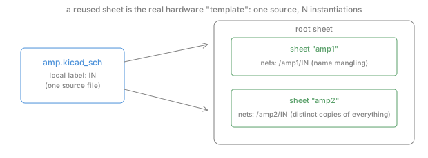
| Reused hierarchical sheet | a module instantiated N times, with name mangling |
| MPN | an exact pinned artifact (lodash@4.17.21) |
BomLine |
the lockfile |
| Datasheet | vendor prose documentation for a closed-source dependency |
PartSpec |
the hand- or machine-written .d.ts type stub for that dependency |
LimitKind |
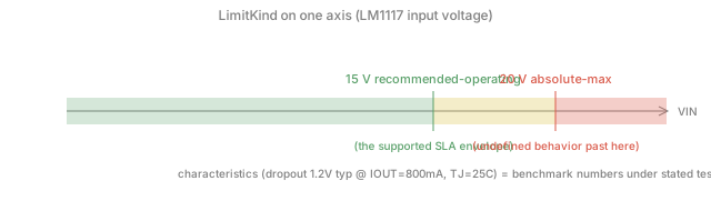
UB boundary / SLA envelope / benchmark numbers |
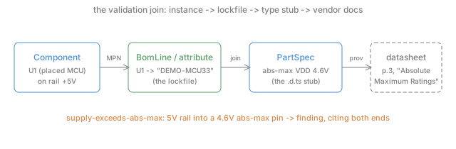
| The validation join | type-checking call sites against dependency stubs via the lockfile |
| doc-IR | the parsed AST of the vendor docs |
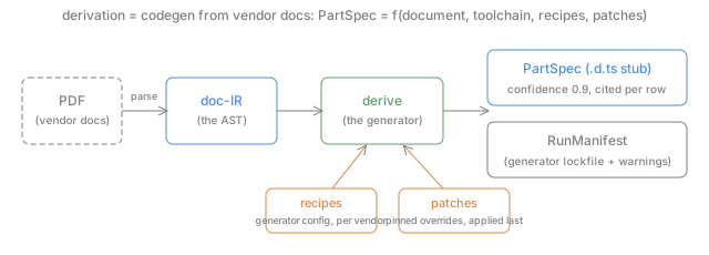
| derive, recipes, patches, manifests | the codegen tool, its config, pinned overrides, and its lockfile |
| Geometry sidecar | source maps |
| Provenance | blame / debug symbols |
Modules and classes: PartLibrary and PartType 
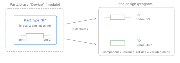
Software. import Device brings in a package. Device.R is a class it declares, with two
members (pins 1 and 2), each typed passive. The class says nothing about any particular
resistor in your program, and nothing about which physical artifact will eventually satisfy it.
Circuit. The schematic’s symbol library. A KiCad lib_symbols entry or an EDIF cell holds
the drawn body, the pin list, each pin’s electrical type (input, output, power_in…), and the
designator prefix (“R” for resistors). Every resistor you place comes from this one definition.
Schema. ir.PartLibrary holding ir.PartTypes. Pins are ir.Pin with an
ir.PinDirection. Readers fill these from the design file itself (v6+ KiCad files embed their
libraries, like vendoring your dependencies).
Instances: Component 
Software. r1 := Device.R(value: "10k"). The variable name is the
reference designator.
Constructor arguments and fields are the instance attributes (Value, MPN/Manufacturer). Twenty
resistors are twenty instances of one class.
Circuit. A placed part: R1 near the connector, R2 in the feedback path. Identity is the ref des, not the position. The same R1 exists in the schematic, the layout, and the BOM.
Schema. ir.Component with RefDes, Attributes, and Sections referencing the
PartType by name. The checks quantify over Components, the way an analyzer walks call sites,
not declarations.
Partial views: ComponentSection 
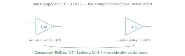
Software. One object whose interface is used at several distinct sites: think of destructuring a struct’s fields across two files, or a partial class. There is still exactly one identity.
Circuit. A dual op-amp: one physical TL072 drawn as two triangles, U1A on this half of the sheet and U1B on that one. One package on the board, one BOM line, two drawn units.
Schema. One ir.Component (“U1”) with two ComponentSections (unit indexes 0 and 1). A
repeated unit index is a genuine bug and trips the duplicate-ref-des diagnostics. Distinct
units never do.
Aliasing: Net 
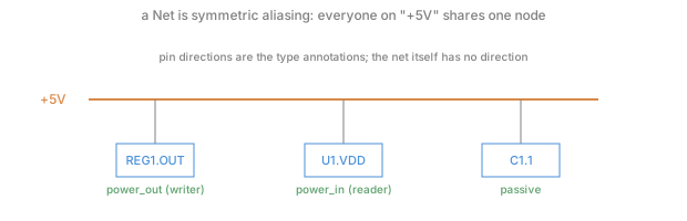
Software. Not a function call. A net is a shared channel, or many variables aliasing one memory cell. Everything attached to “+5V” IS the same electrical node. There is no caller and no callee, no direction on the edge itself.
Circuit. The +5V rail, where the regulator’s output pin, the MCU’s VDD pin
and a decoupling cap are all tied together.
Directionality lives on the pins. The regulator’s pin is power_out, the MCU’s is power_in.
Those are the type annotations the connectivity rules dispatch on, and a missing direction means
skip rather than guess.
Schema. ir.Net with Connections (component ref + pin ref). Pin directions come from the
PartType.
Name resolution: net solving 
Software. Compilation’s front half. The source (wires, labels, junctions, geometry) contains only implicit references, and the solver builds the symbol table of which tokens denote the same thing. Two labels “+5V” on different wires are two mentions of one symbol. The solver unifies them, exactly like a linker unifying external symbols by name.
Circuit. KiCad stores no netlist. Connectivity is the drawing. A wire
endpoint on a pin’s connect point binds. A label names the node. Same-named power symbols merge
across the sheet. Getting these binding rules right is a language-semantics problem, so they are
pinned against the reference implementation (kicad-cli), the way a compiler pins against a
conformance suite. The full binding rules are in
Net solving and hierarchy.
The protection walk: Reach 
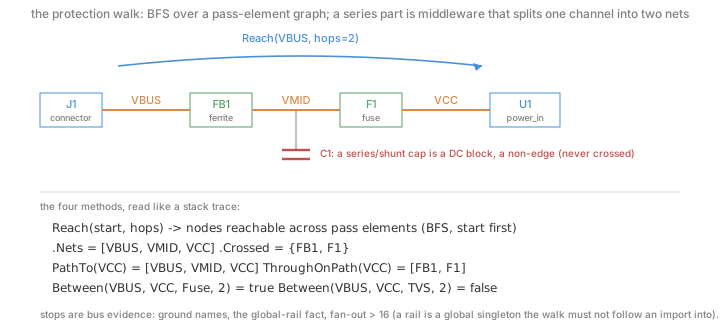
Software. Some questions are not about one node but about a path. Is there an auth middleware
anywhere between the public handler and the database call? Neither endpoint can answer that. You
walk the call graph between them. Reach is that walk. A two-terminal series part (a resistor,
inductor, ferrite bead, or fuse) is inline middleware. It splits one logical
channel into two named nets, so a per-net rule is blind across it.
Reach(start, hops) is a bounded BFS over the pass-element adjacency, and the helpers read the
result like a stack trace. PathTo is the path, ThroughOnPath is the middleware crossed in order,
and Between(from, to, class, hops) is the one-line “does any X sit on the path” query.
Why a series capacitor is a non-edge and a rail is a stop
Two edges of the model carry the electrical meaning. A series capacitor is a DC block, an insulator between two plates, so it is a non-edge and the walk never crosses it (a decoupling cap to ground is a different role entirely).
A rail is a global singleton. Ground, the design-wide global fact, or any net with bus-scale
fan-out (more than 16 pins) is a stop, because following a pull-up onto VCC
would make the whole design reachable. That is the graph equivalent of chasing an import into a
global and treating everything it touches as local.
Circuit. Protection and presence rules are reachability questions. A fuse sits somewhere between the connector and the regulator. An ESD clamp hangs off a net on the power-entry path. The series element that splits the net is exactly what a per-net check cannot see past, which is why the walk exists.
Schema. check.Model.Reach/Between over the netlist IR. The crossable classes are
resistor, inductor, ferrite, and fuse. The stops are ground, global, and high
fan-out.
Templates: the reused sheet 
Software. Real templates (C++ or generics) specialize at compile time, and each
instantiation is a new type. The hardware analog is not the parameterized part. A Device:R
with Value: 10k is just a constructor argument, and no specialization happens. The true
template is the reused hierarchical sheet. One amp.kicad_sch source instantiated twice
produces two complete copies of everything inside, with per-instance qualified names (/amp1/IN,
/amp2/IN). That is name mangling, letter for letter.
Circuit. A stereo preamp drawn once and instantiated per channel. A motor driver repeated four times. Each instance has its own components (the walk resolves per-instance reference designators) and its own local nets.
Schema. ir.Sheet references plus the multi-sheet hierarchy walk. Qualified net names follow
KiCad’s own convention so they match board-file names.
The lockfile: MPN and BomLine 
Software. Your code says import leftpad. The lockfile says leftpad@1.3.0, sha512-....
The MPN is that exact pinned artifact. “BSS138” names one orderable product with one datasheet,
not “some N-FET”. BomLine (or the MPN attribute on a component) is the lockfile entry binding
your variable to it.
Circuit. The BOM says R1 will be built as Yageo RC0603FR-0710KL. Two designs can place identical schematics and ship different physical parts, and only the BOM knows. This is also the moment of real specialization (see Templates). Choosing the MPN is link-time binding of the abstract symbol to a concrete implementation.
Schema. ir.BomLine{ref_des, mpn, manufacturer}. The KiCad reader carries MPN and
Manufacturer symbol properties into component attributes as the no-BOM fallback. The join is
case-insensitive on MPN and nothing fuzzier. A near-miss MPN is a different part until a human
says otherwise.
Vendor docs as type stubs: PartSpec 
Software. The dependency is closed-source (you will never see the die), and the vendor
publishes prose documentation. A PartSpec is the .d.ts stub someone wrote for it. It carries
machine-readable claims about the artifact’s limits and behavior, written against one pinned doc
revision (SourceDoc), with every claim linking back to the prose it came from (page, table,
extraction method, confidence). Like DefinitelyTyped, stubs start hand-written (the fixtures) and
graduate to generated (derive). A stub no one has verified is not trusted, because it can look
authoritative without being so.
Circuit. “Absolute-maximum VDD is 4.6 V (page 3, Absolute Maximum Ratings, TA = 25 °C).” A parameter is never a bare scalar. It is a min/typ/max range valid under stated test conditions, at a stated limit kind.
Schema. param.PartSpec / Parameter / Condition / ParamProvenance (see the
datasheet layer). The honesty predicates are part of the
contract. UnderSpecified means the conditions are not trustworthy, so skip. MachineComparable
means a text-only condition should go to a human rather than an automatic comparison.
Limits as contract tiers: LimitKind 
Software.
- Absolute-max is the undefined-behavior boundary. Past it, the vendor promises nothing. Like indexing past the end of an array, damage may be immediate or latent.
- Recommended-operating is the supported envelope. The SLA. Inside it, the product behaves as documented.
- Characteristic is published benchmark numbers. Measured behavior under a stated config, and like any benchmark, the number is meaningless without the config (the test conditions).
Circuit. Take the LM1117. Operate VIN up to 15 V (recommended), never exceed 20 V (absolute max), expect ~1.2 V dropout at 800 mA and 25 °C (characteristic).
The type checker: the validation join 
Software. With stubs (PartSpecs), a lockfile (BOM/MPN), and call sites (Components), checking becomes linting. Resolve each call site through the lockfile to its stub and verify usage against the declared types. If a dependency has no stub, the check is skipped rather than silently passed. A missing stub means the usage is unchecked, not that it is correct.
Circuit. Consider supply-exceeds-abs-max. A power-input pin on a rail whose name says
“+5V”, joined to a part whose stub says absolute-max supply is 4.6 V, is a finding that cites
both ends, the schematic location and the datasheet page.
Schema. The check Model’s params tier (check.NewModelWithParams, Model.PartSpec), the
supply-symbol alias map (vendor spellings live in the model layer, never in rule text), and the
rule itself. An empty param.ParamSet yields no findings by construction, so a missing tier is
silent rather than a false pass.
Codegen: doc-IR and derive 
Software. Generating stubs from vendor docs is a compiler pipeline:
- doc-IR is the parsed AST of the documentation, tables, cells, figures, text, with positions (see the datasheet layer). N parsers produce it, and nothing downstream re-reads the PDF.
- derive is the generator: deterministic, versioned, reproducible (see the datasheet layer).
- recipes are the generator’s per-vendor config (“in TI sheets, this heading means absolute-max”), data in git, reviewed like code.
- patches are pinned human overrides that survive regeneration, the fix you commit so the generator’s known mistake on one exact input can never come back.
- the RunManifest is the generator’s lockfile plus its warnings. Inputs are pinned, and every gap (what it saw and did not extract) is enumerated, so a gap is recorded rather than passing as coverage.
Circuit. A real run. Docling parsed the BSS138 sheet and derive emitted 30 parameters with page citations. On the LM1117 sheet the parser mis-placed one value into the wrong column, and a two-patch pair (clear plus insert) corrects it permanently.
Source maps and blame: geometry and provenance 
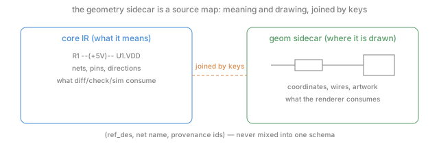
Software. The geometry sidecar is a source map. It maps the same program to where things are drawn, kept out of the semantic schema and joined by keys. The renderer consumes it and the analyzers never do. Provenance is blame and debug symbols. Every IR node, finding, and extracted parameter can answer which file and line (or page and table) it came from, and that answer makes a finding verifiable rather than asserted.
Circuit. Click a finding, land on the exact wire in the schematic. Click a datasheet-backed limit, land on the exact table in the PDF.
Schema. geom.SchematicGeometry joined by ref_des/net/provenance keys (see
Geometry and rendering). ir.Provenance and
param.ParamProvenance carry the source keys.
Where the analogy breaks (on purpose) 
- No dynamic dispatch, no open world. Every connection is resolved at design time, and the whole program is one closed compilation unit. That is why exhaustive static checking works at all, and why “the design” can be diffed as a value.
- Nets are symmetric. There is no caller. Electrically everyone on the net calls everyone. Direction is a property of pins, not edges, so pin directions do the type-annotation work and their absence means skip.
- Runtime is physics. There is no sandbox. Running the program means powering a board, so the linting tier (checks against stubs) carries weight software linters do not. It is the cheap static end of a ramp whose expensive end is simulation.
- Instances are atoms. Two “identical” resistors are still two physical objects with tolerances, and the stub describes a population, not your unit. That is what tolerance analysis exists to reason about, and why characteristics carry min/typ/max rather than one number.