1. What a board is made of, and why
A board is a few kinds of part doing about twenty jobs. How to tell which job, from the schematic alone.
Open an unfamiliar schematic and it looks like several hundred arbitrary components. It is not, and the gap between those two impressions is most of what separates someone who can read a board from someone who cannot.
Two facts close it. A board is made of very few kinds of thing. And each of those things is doing one of a small number of recurring jobs, which you can usually identify from what it connects to.
Prerequisites: EE1. You know that a resistor resists, a capacitor stores charge, and a chip does something complicated in the middle.
Levels on this page: EE1, EE2, EE3. Each links to what that level means.
A board is a few kinds of thing (EE1) 
Here is the board the rest of this chapter asks questions about. You are not meant to read it yet, only to notice how few kinds of thing are on it:
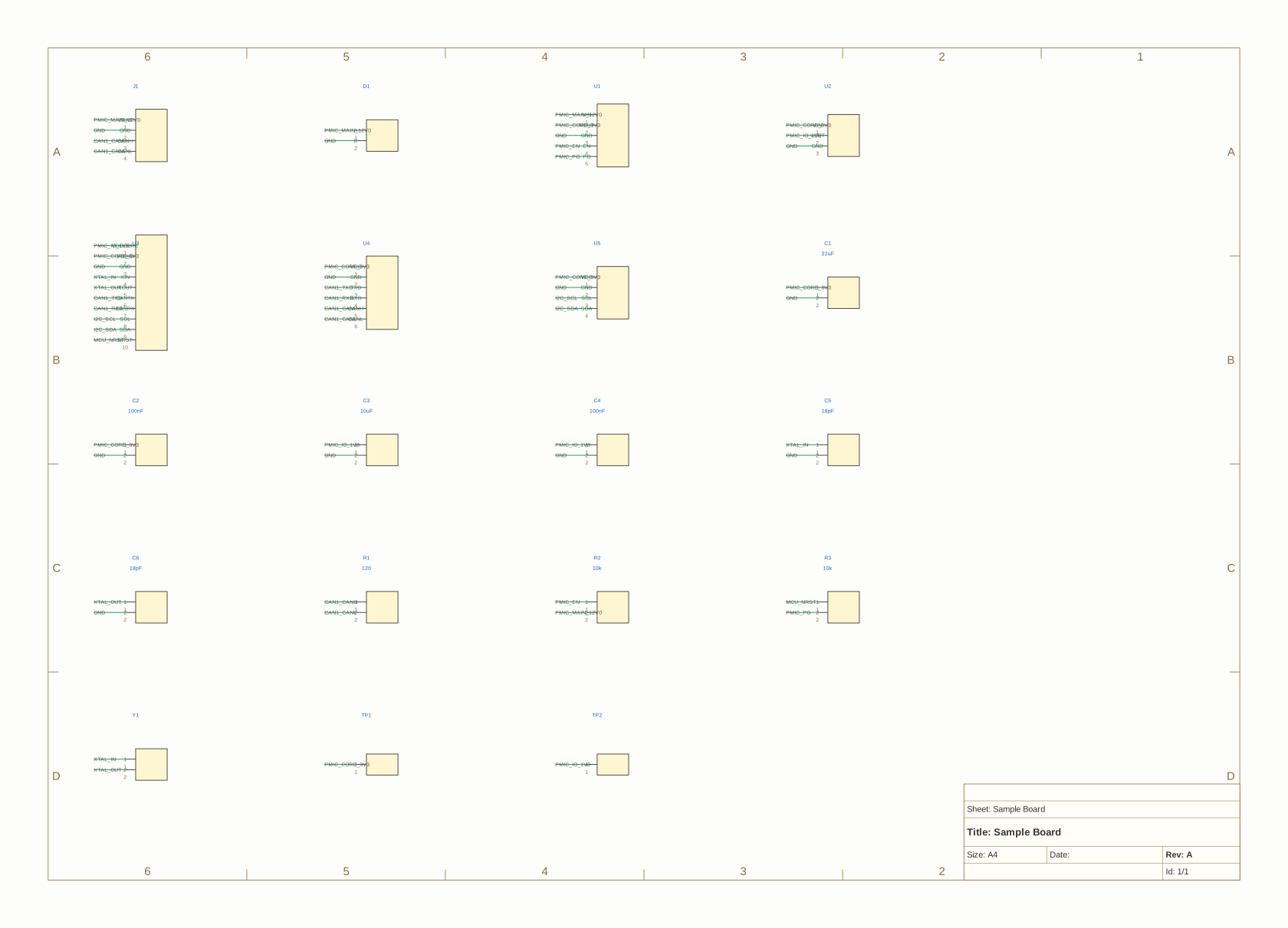
That drawing came from agni render examples/tutorial-project/designs/gateway, which is worth knowing early: pointing the tool at a design rather than at a file lets it use whichever artifact answers the question, and for a picture that is the schematic the design declares.
Now ask what is actually on it:
$ agni query examples/tutorial-project/designs/gateway/gateway.edn 'component.class(?r, ?c) => ?r, ?c'
r    c           provenance
C1   capacitor   designs/gateway/gateway.edn
C2   capacitor   designs/gateway/gateway.edn
C3   capacitor   designs/gateway/gateway.edn
C4   capacitor   designs/gateway/gateway.edn
C5   capacitor   designs/gateway/gateway.edn
C6   capacitor   designs/gateway/gateway.edn
D1   diode       designs/gateway/gateway.edn
D1   tvs         designs/gateway/gateway.edn
J1   connector   designs/gateway/gateway.edn
R1   resistor    designs/gateway/gateway.edn
R2   resistor    designs/gateway/gateway.edn
R3   resistor    designs/gateway/gateway.edn
TP1  test_point  designs/gateway/gateway.edn
TP2  test_point  designs/gateway/gateway.edn
U1   ic          designs/gateway/gateway.edn
U1   regulator   designs/gateway/gateway.edn
U2   ic          designs/gateway/gateway.edn
U2   regulator   designs/gateway/gateway.edn
U3   ic          designs/gateway/gateway.edn
U4   ic          designs/gateway/gateway.edn
U5   ic          designs/gateway/gateway.edn
Y1   clock       designs/gateway/gateway.edn

22 result(s)
Twenty-two rows covering nineteen parts, and only nine distinct kinds: capacitor, resistor, diode, tvs, connector, test point, ic, regulator, clock. A real board has hundreds of parts and roughly the same vocabulary, plus inductors, ferrites, transistors and a fuse. The part count grows; the number of kinds barely moves.
Three details in that output are worth noticing now.
There are more rows than parts. D1 appears twice, as diode and as tvs, and U1 and U2 each appear as ic and as regulator. Class is a family tag rather than a single label, because a TVS diode genuinely is a diode and rules want to reason at both levels: a rule about reverse current cares that it is a diode, and a rule about ESD protection cares that it is specifically a TVS.
U3, U4 and U5 are only ic, with no second tag. The tool cannot tell what kind of chip they are, and that is honest rather than broken. Their part numbers say exactly what they are (ACME-MCU-G1, ACME-CAN-XCVR, ACME-EEPROM-4K), so a processor, a CAN transceiver and a memory. But that identity lives in the part number and the datasheet, not in the connections, and a netlist reader that guessed “MCU” from a string would be wrong the first time it met a part named differently.
This is the first thing you will meet that a netlist genuinely cannot answer, and the tool’s response is the pattern for all of them: the information gets declared rather than inferred. U4 is known to be a CAN device because the design carries an interface: CAN property on it, which the board’s interface profile then checks against what CAN requires. That is chapter 10.
Half the board is capacitors and resistors. Nine of the nineteen parts, and that is low only because this is a small teaching fixture. On a real board the passives are usually eighty to ninety percent of the part count, and they are exactly the parts that look arbitrary. The rest of this chapter is about them.
The same part, different jobs (EE2) 
Here is where the instinct starts. Ask for every resistor with its part number and the nets it touches:
$ agni query examples/tutorial-project/designs/gateway/gateway.edn 'component.class(?r, "resistor"), component.mpn(?r, ?m), component-on-net(?r, ?n) => ?r, ?m, ?n'
r   m              n               provenance
R1  ACME-RES-120R  CAN1_CANH       designs/gateway/gateway.edn ; designs/gateway/gateway.edn:CAN1_CANH
R1  ACME-RES-120R  CAN1_CANL       designs/gateway/gateway.edn ; designs/gateway/gateway.edn:CAN1_CANL
R2  ACME-RES-10K   PMIC_EN         designs/gateway/gateway.edn ; designs/gateway/gateway.edn:PMIC_EN
R2  ACME-RES-10K   PMIC_MAIN_12V0  designs/gateway/gateway.edn ; designs/gateway/gateway.edn:PMIC_MAIN_12V0
R3  ACME-RES-10K   MCU_NRST        designs/gateway/gateway.edn ; designs/gateway/gateway.edn:MCU_NRST
R3  ACME-RES-10K   PMIC_PG         designs/gateway/gateway.edn ; designs/gateway/gateway.edn:PMIC_PG

6 result(s)
Three resistors. Two of them are the same value, 10k. All three are doing completely different jobs, and you can work out each one from that table alone, without opening the schematic.
R1 (120Ω) sits between CAN1_CANH and CAN1_CANL. Those two nets are the two halves of a differential pair, and a resistor bridging a pair is a termination. A CAN bus is a transmission line, and a signal reaching the far end of an unterminated line reflects back down it and collides with what follows. The terminator absorbs it. 120Ω is not a coincidence: it is the characteristic impedance the CAN standard specifies, and the board’s CAN profile declares the requirement ({type: termination, params: {high: _CANH, low: _CANL}}).
R2 (10k) sits between PMIC_EN and PMIC_MAIN_12V0. One end is an enable pin, one end is a rail. A resistor from a signal to a rail is a pull-up: it holds the signal high when nothing else is driving it. Here that means the power management chip is enabled by default at power-on, rather than waiting for someone to assert it.
R3 (10k) sits between MCU_NRST and PMIC_PG. Both ends are signals: a reset line and a power-good line. A resistor in series between two signals is doing neither of the above. It is a series resistor, letting the power-good output hold the processor in reset until the rails are up, while limiting the current if the two ever fight.
Same class, two of them the same value, three jobs. The value tells you almost nothing on its own. What it connects to tells you nearly everything.
The decision procedure (EE3) 
That is generalisable, and it is the single most useful habit at this level. For a two-terminal part, look at what is on each end:
| One end | Other end | It is probably a | Why |
|---|---|---|---|
| signal | rail | pull-up | holds the line high when undriven |
| signal | ground | pull-down | holds the line low when undriven |
| signal | the other half of a pair | termination | absorbs the reflection at the end of a line |
| signal | a different signal | series resistor | damping, current limit, or isolation |
| rail | ground | decoupling or bulk cap | local charge reservoir (chapter 3) |
| rail | a different rail | filter or protection | ferrite, fuse, or an OR-ing diode |
| signal | ground, and it is a cap | filter | shunts high-frequency noise away |
| pin of a crystal | ground | load capacitor | sets the oscillator’s operating point |
Two things make this work. Net names carry intent, because engineers name nets after what they are for, which is why the tool has a whole naming conventions layer. And a part’s class plus its topology is nearly always enough, which is exactly why so many rules in the catalog are shaped as “a part of class X on a net of kind Y”.
When the procedure does not settle it, that is information too. A resistor between two signals could be damping a fast edge, limiting current into a protection diode, or a footprint nobody stuffed. A netlist cannot tell those apart, and the honest rules in this catalog say so rather than guessing. That is what a not-considered verdict is.
The recurring jobs (EE3) 
The full working list. You do not need to memorise it; you need to know it is short and finite, so that an unfamiliar part is a lookup rather than a mystery.
Holding a line at a known level. Pull-up, pull-down. Needed because a line that nothing drives has no defined voltage, which is a genuinely surprising fact and is chapter 4’s subject. → floating-input, i2c-pull-up, profile/missing-pullup
Supplying charge locally. Decoupling capacitor at each supply pin, bulk capacitor per rail. → decoupling-present, bulk-cap (chapter 3)
Making a signal the right size. Voltage divider (two resistors, tap in the middle), current limit (in series with an LED or an input), level shift between two logic voltages. → led-polarity
Taming an edge. Series damping resistor, ferrite bead between a noisy domain and a quiet one, snubber across a switch. Everything here exists because a fast edge is also a radio transmitter.
Ending a transmission line. Termination across a differential pair or to ground at the end of a bus. → profile/termination
Configuring at boot. Strap resistors that encode a number the chip latches at reset, and zero-ohm links that make an option selectable at build time. → the design-intent strap rules, strap-address-collision (chapter 9)
Surviving the outside world. TVS or ESD clamp on anything reaching a connector, reverse-polarity protection on the input, a fuse. → profile/esd, esd-protection
Measuring. A shunt resistor turns a current into a voltage you can read; a divider scales a voltage into an ADC’s range.
Keeping time. A crystal plus two load capacitors, or an oscillator that packages both. → crystal-load-caps, resonator-redundant-load-caps (chapter 11)
Moving energy. The inductor in a switching regulator, storing and releasing energy every cycle. This is the one job where the part is not incidental to the circuit but the point of it.
That is about twenty, depending how you count, and it covers the overwhelming majority of the small parts on any board you will open.
What the chips are doing 
The list above is about the small parts, because they are the ones that look arbitrary. The chips are usually self-evident from their part number, and fall into a few roles: a processor or controller that runs the software, regulators that make the rails, transceivers that convert between a chip’s logic levels and a bus’s electrical standard, memory, sensors, and connectors as the boundary with everything off-board.
The useful instinct here is that the small parts exist to serve the chips. Every resistor and capacitor on a board is there because some chip’s datasheet asked for it, or because a signal between two chips needed conditioning. When you cannot work out why a passive is present, the question to ask is “which chip needed this, and what for”.
What you can now answer 
- Roughly how many kinds of thing are on a board, and why the list does not grow with board size. (EE1)
- Why the same 10k resistor is doing two different jobs in two places. (EE2)
- Given a two-terminal part and the nets on each end, what job it is probably doing. (EE3)
- Why a netlist sometimes cannot tell, and why that is reported rather than guessed. (EE3)
The rules this page explains 
None on its own, which a chapter 1 has no business claiming. It supplies the vocabulary the rest of the catalog is written in. Run the two queries above against any board you are handed, in that order, as the fastest way to orient yourself in an unfamiliar design.
Next: the drawing is not the circuit, on the ways a schematic can show a connection that does not exist and hide one that does.