6. Parts that care which way round
Most components have no orientation. The ones that do fail in obvious ways, and the same wiring is a defect on one part and correct on another.
The shortest chapter in the course, and the one with the most visible failure mode.
Prerequisites: Chapter 1 for reading a part from what it connects to.
Levels on this page: EE3, EE4. Each links to what that level means.
Most parts do not care (EE3) 
A resistor works the same either way round. So does a ceramic capacitor, an inductor, a fuse, most connectors’ shells. You can rotate them on the board and nothing changes, which is why nobody thinks about orientation most of the time.
A minority do care, and they announce it in the symbol: one pin is marked differently from the other. The recurring ones are diodes of every kind, polarised capacitors (electrolytic and tantalum), and anything with a keyed connector body.
The consequences are not equal. A backwards LED does not light. A backwards rectifier stops the circuit working. A backwards tantalum capacitor is the one that matters most, because tantalums fail short and can vent or burn, so the mistake destroys the part and sometimes its neighbours.
Here is one, wired backwards (EE3) 
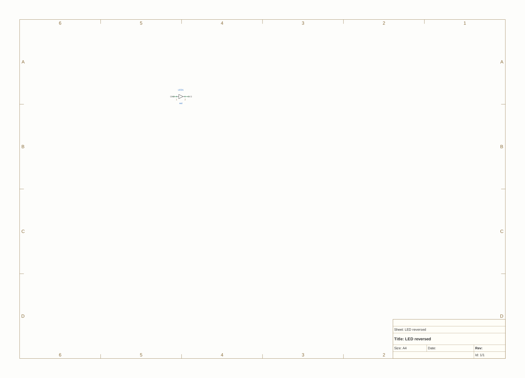
Current flows through a diode from anode to cathode and not the other way. This one has its anode on ground and its cathode on the rail, so the only direction it could conduct is the direction it is blocking.
$ agni check --verdicts --rule led-polarity cmd/agni/testdata/conformance/ledpol.fires.kicad_sch
led-polarity  1 fail
    fail  LED1  LED anode is on ground and cathode on a power rail; it can never conduct

1 verdicts across 1 rule(s), 1 fail
Read the witness rather than the rule name. “It can never conduct” carries the entire finding, and you can check it against the drawing without knowing anything about the tool.
The severity is error, consistent with chapter 4: this is not a reliability risk, it is a thing that does not work. The board will be built, the LED will be soldered on, and it will never light on any unit.
Worth noticing what makes it expensive despite being obvious. The rule’s own Impact says it: the part passes every connectivity check, because both pins are wired to something. Nothing about the netlist looks wrong. It survives assembly and shows up at bring-up as a dead indicator, which is a part-level rework for a slip made during capture.
The same wiring, on a different part, is correct (EE4) 
Here is where it gets interesting, and it is the reason this rule is narrower than it looks.
led-polarity is deliberately LED-only. Not “diode reversed”. The reason is on the tutorial board:
$ agni query examples/tutorial-project/designs/gateway/gateway.edn 'component.class(?r, "tvs"), component-on-net(?r, ?n) => ?r, ?n'
r   n               provenance
D1  GND             designs/gateway/gateway.edn ; designs/gateway/gateway.edn:GND
D1  PMIC_MAIN_12V0  designs/gateway/gateway.edn ; designs/gateway/gateway.edn:PMIC_MAIN_12V0

2 result(s)
$ agni check --verdicts --rule led-polarity examples/tutorial-project/designs/gateway/gateway.edn
No rule reported a considered set. Only some rules state one; see --verdicts.
D1 is a TVS diode sitting between GND and the 12V rail. That is the same topology the rule just called a defect: a diode across a supply, oriented so it does not conduct. On a TVS that orientation is the point. A protection diode sits there doing nothing at all until a voltage spike arrives, at which point it conducts and clamps the spike to a level the rest of the board survives. A TVS that conducted in normal operation would be a short across the rail.
Zeners are the same story. A zener is used in reverse breakdown, which is a region ordinary diodes are specified never to enter.
So the second command reports nothing, because the rule’s scope is component.class == led and there is no LED on that board. A rule that flagged “diode reversed” generally would fire on every TVS and every zener on every design, and a check that is wrong most of the time gets muted, after which it catches nothing at all.
That is worth holding on to as a general point about checks rather than about diodes. A topology means different things on different parts. Deciding correctness needs to know what the part is, and establishing part identity before asking anything else is most of what this tool spends its effort on.
What the tool has to know (EE3) 
To make this judgement at all, two separate facts have to be available, and both come from outside the connectivity graph.
Which pin is the anode. That is a pin role, and it comes from the symbol. A symbol that types its pins as two anonymous passives leaves nothing to reason about.
Which net is ground and which is a rail. That comes from naming conventions, the layer chapter 1 mentioned and the tutorials cover in rung 4. A net called GND is ground by convention rather than by anything electrical in the netlist.
Take either away and the check cannot run. That is the honest boundary, and it is why the rule reasons from rail names rather than from current direction. Knowing which way current is meant to flow through an arbitrary diode is a fact no netlist carries.
What you can now answer 
- Which parts have an orientation, and which of them are dangerous rather than merely broken. (EE3)
- Why a reversed LED passes every connectivity check on the board. (EE4)
- Why the same diode-across-a-rail topology is a defect on one part and correct on another. (EE4)
- What two facts a polarity check needs, and where each comes from. (EE3)
The rules this page explains 
| Rule | Severity | What it catches |
|---|---|---|
led-polarity |
error | an LED whose anode is on ground and cathode on a rail |
One rule, hence the short chapter. The general version, covering rectifiers and polarised capacitors, needs a fact about intended current direction that no netlist carries.
Next: reading a datasheet like a type signature, where the course crosses from what a netlist can tell you into what only a document can.